Introduction
This is the third and last post in the series I am creating, based on the logic from Physics-based Solar System Lessons:- Gravity Part 1: An update
- Gravity Part 2: Orbit predictions (One-Body problem)
- Gravity Part 3: Create a force map and display it (CPU, Compute Shader and Fragment Shader)
Gravity Part 3: Create a force map and display it
In Gravity Part 1 I polished a system that creates movement out of objects due to their gravitational force. Wouldn't it be interesting to visualize these forces somehow? This is not difficult but has a very big problem: these calculations need to be reevaluated every frame and then painted to a texture.

|
| Artistic color representation for force direction by Shutterstock |
To visualize this, I created 3 independent systems that calculate the gravity forces and then paint the texture:
- CPU: CPU calculation, CPU painting.
- Compute Shader: Compute Shader calculation, CPU painting.
- Fragment Shader: Fragment Shader calculation, Fragment Shader painting.
Initial Setup
First we need to create a Plane with the dimensions we want it to cover, and
then attach the desired script to be used. The beautiful thing about the
current approach is that the initial setup is almost the same for each case
of texture painting.
- CPU: enable script. Material set to Unlit/Texture.
- Compute shader: enable script. Material set to Unlit/Texture.
- Fragment Shader: enable script. Material set to Gravity/ForceMap.
For easier visualization check the following screenshots:

|
| Setup for CPU/Compute Shader scripts and texture |

|
| Setup for Fragment Shader script and texture |
General remarks
\[F = G\dfrac{m_1 m_2}{r^2}\]
If we just use these values to paint, we will mostly see a bright color area around large gravity sources and everything else will be mostly blackish. By using a logarithm scale, we can see more clearly the dominant force direction in each point. If the color is close to black, then there is virtually no net force (specially in a Log scale).

|
| Log(x) by WolframAlpha |
Color representation: I will be using an RGB color representation to
visualize 4 force directions (we are painting on a 2D plane, so we will
ignore anything from the third axis):
How to paint pixels in a texture. Technically there are two easy ways to change pixels in a texture in Unity [1]:
CSForceMap.compute
The other piece of code has a very similar logic to the previous implementation using only CPU:
It is worth noting that there is a maximum thread group count of 65535 (with a group of 32 the maximum texture size is 1448x1448, with a group of 64 the maximum texture size would be 2047x2047) that can be used. My code has a group of 32 and I will be using the texture of 1448x1448 in the comparisons.
Similar to the CPU case we can also add a timer to update the texture at specified moments. This improves performance slightly.
- Red: Force towards “left” of texture.
- Green: Force towards “right” of texture.
- Blue: Force towards “top” of texture.
- Yellow: Force towards “bottom” of texture.

|
|
Directions of forces are represented by colors |
Black means neutral direction of force.
CPU
This is the simplest approach; I directly use the logic I had already created in previous posts. For simplicity I redesigned all the logic within the same script, so everything is just in one place. The logic is:- Initialization:
- Setup texture size and properties.
- Create world points for the texture.
- Update texture:
- Calculate forces: For each texture pixel get the net force.
- Paint forces: For each net force paint in the texture with a certain color
- Update texture from painted pixels.
1 2 3 4 5 6 7 8 9 10 11 12 13 14 15 16 17 18 19 20 21 22 23 24 25 26 27 28 29 30 31 32 33 34 35 36 37 38 39 40 41 42 43 44 45 46 47 48 49 50 51 52 53 54 55 56 57 58 59 60 61 62 63 64 65 66 67 68 69 70 71 72 73 74 75 76 77 78 79 80 81 82 83 84 85 86 87 88 89 90 91 92 93 94 95 96 97 98 99 100 101 102 103 104 105 106 107 108 109 110 111 112 113 114 115 116 117 118 119 120 121 122 123 124 125 126 127 128 129 130 131 132 133 134 135 136 137 138 139 140 141 142 143 144 145 146 147 148 149 150 151 152 153 154 155 156 157 158 159 160 161 162 163 | using System; using System.Linq; using UnityEngine; public class ForceMapCpu : MonoBehaviour { [Header("Texture details")] [SerializeField] private Vector2 _textureResolution = new Vector2(1000, 1000); [Tooltip("Regardless of texture Y position, do the calculations as if Y = value")] [SerializeField] private float _positionTextureY = 0; private Texture2D _texture; private Color[] _texturePixelsColor; //All the points in the texture with a set color in each pixel private Vector3[] _texturePixelPositions; //Each Pixel in the texture is mapped to a world coordinate private float _maxForce; //Used to clamp the force visualization private SpaceObject[] _spaceObjects; private float _time; private float _waitSeconds = 0.01f; void Start() { _time = Time.realtimeSinceStartup; var spaceObjects = GameObject.FindGameObjectsWithTag("SpaceObject").Where(o => o.gameObject != gameObject).ToList(); _spaceObjects = spaceObjects.Select(p => p.GetComponent<SpaceObject>()).ToArray(); _maxForce = GetMaximumGravity(); _texture = new Texture2D((int)_textureResolution.x, (int)_textureResolution.y) { wrapMode = TextureWrapMode.Clamp, filterMode = FilterMode.Bilinear }; GetComponent<Renderer>().material.mainTexture = _texture; _texturePixelsColor = new Color[_texture.height * _texture.width]; _texturePixelPositions = GetTextureWorldPoints(); } void Update() { if (_time + _waitSeconds <= Time.realtimeSinceStartup) { PaintForceMap(); _time = Time.realtimeSinceStartup; } } private float GetMaximumGravity() { var maxForce = float.MinValue; foreach (var spaceObject in _spaceObjects) { var force = GetGravity(spaceObject, spaceObject.transform.position + new Vector3(1.0f, 1.0f, 1.0f)); if (maxForce <= force.magnitude) { maxForce = force.magnitude; } } return maxForce; } // Apply Log to the gravity to ease visualization of the force private Vector3 GetGravity(SpaceObject spaceObject, Vector3 atPoint) { var direction = spaceObject.transform.position - atPoint; var gravityLog = Math.Log(1 + spaceObject.GetGravitationalPullForce(direction.magnitude)); return direction.normalized * (float)gravityLog; } private Vector3[] GetTextureWorldPoints() { var worldPoints = new Vector3[_texture.height * _texture.width]; for (int i = 0; i < _texture.height; i++) { for (int j = 0; j < _texture.width; j++) { var localPoint = TransformTextureCoordinateToLocalCoordinates(i, j, _texture); var worldPoint = transform.TransformPoint(localPoint); worldPoint.y = _positionTextureY; //We want to check with respect to reference planet (usually Earth) and not actual position of texture worldPoints[j * _texture.height + i] = worldPoint; } } return worldPoints; } // From i,j position in texture to a local Vector3 private Vector3 TransformTextureCoordinateToLocalCoordinates(int i, int j, Texture2D texture) { var posX = 5 - 10 * (i + 0.5f) / texture.height; var posZ = 5 - 10 * (j + 0.5f) / texture.width; return new Vector3(posX, 0, posZ); } private void PaintForceMap() { for (int i = 0; i < _texture.height; i++) { for (int j = 0; j < _texture.width; j++) { var clampedForce = GetGravityAtPoint(_texturePixelPositions[j * _texture.height + i]) / _maxForce; var color = GetColorFromForce(clampedForce); _texturePixelsColor[j * _texture.height + i] = color; } } _texture.SetPixels(_texturePixelsColor); _texture.Apply(); } private Vector3 GetGravityAtPoint(Vector3 point) { var netForce = new Vector3(); foreach (var spaceObject in _spaceObjects) { var force = GetGravity(spaceObject, point); netForce += force; } return netForce; } private Color GetColorFromForce(Vector3 force) { var colorForce = Color.black; if (force.z > 0.0f && force.x > 0.0f) { colorForce.b = force.z; colorForce.g = force.x; } else if (force.z > 0.0f && force.x <= 0.0f) { colorForce.b = force.z; colorForce.r = -force.x; } else if (force.z <= 0.0f && force.x > 0.0f) { colorForce.r = -force.z; colorForce.g = Mathf.Sqrt(Mathf.Pow(force.z, 2) + Mathf.Pow(force.x, 2)); } else if (force.z <= 0.0f && force.x <= 0.0f) { colorForce.r = Mathf.Sqrt(Mathf.Pow(force.z, 2) + Mathf.Pow(force.x, 2)); colorForce.g = -force.z; } return colorForce; } } |
How to paint pixels in a texture. Technically there are two easy ways to change pixels in a texture in Unity [1]:
- SetPixel: only sets 1 pixel at a time.
- SetPixels: set a whole block of pixels. I used this as it is more efficient in our case.
Optimization
When I first created this script I used small texture sizes, and still got decent framerates (60+ FPS), as I increased the texture size the FPS reduced drastically. One way to optimize it is not to calculate in every update call, but whenever is necessary. That is why I am using a time delay to paint the force map.Compute Shader
The logic here is a bit more complex. We have 2 scripts:- CSForceMap.compute: This is a file that uses shader language and will be ran in the GPU.
- ForceMapComputeShader.cs: This script loads the information into the GPU, retrieves it and then paints it.
CSForceMap.compute
1 2 3 4 5 6 7 8 9 10 11 12 13 14 15 16 17 18 19 20 21 22 23 24 25 26 27 28 29 30 31 32 33 34 35 36 37 38 39 40 41 42 43 44 45 46 47 48 49 50 51 52 53 54 55 56 57 58 59 60 61 | #pragma kernel CSForceMap struct Source { float3 position; float mu; }; //Constants. Set in initialization uint sizeX; uint sizeY; uint numSources; float maxForce; RWStructuredBuffer<float3> pixelPositions; //Dynamic variables RWStructuredBuffer<Source> gravSources; //This gets updated asyncronously RWStructuredBuffer<float4> forcesInColor; //Contains the data to be retrieved from the C# script float4 GetColorFromGravity(float3 force) { float4 colorForce = float4(0, 0, 0, 0); if (force.z > 0.0f && force.x > 0.0f) { colorForce.b = force.z; colorForce.g = force.x; } else if (force.z > 0.0f && force.x <= 0.0f) { colorForce.b = force.z; colorForce.r = -force.x; } else if (force.z <= 0.0f && force.x > 0.0f) { colorForce.r = -force.z; colorForce.g = sqrt(pow(force.z, 2) + pow(force.x, 2)); } else if (force.z <= 0.0f && force.x <= 0.0f) { colorForce.r = sqrt(pow(force.z, 2) + pow(force.x, 2)); colorForce.g = -force.z; } return colorForce; } [numthreads(32, 1, 1)] void CSForceMap(uint3 id : SV_DispatchThreadID) { float3 netForce = float3(0, 0, 0); for (uint k = 0; k < numSources; ++k) { float3 forceDirection = (gravSources[k].position - pixelPositions[id.x]); float gravityLog = log(1 + gravSources[k].mu / dot(forceDirection, forceDirection)); netForce += normalize(forceDirection) * gravityLog; } forcesInColor[id.x] = GetColorFromGravity((netForce / maxForce)); } |
The other piece of code has a very similar logic to the previous implementation using only CPU:
- Initialization:
- Setup texture size and properties.
- Create world points for the texture.
- Initialize Compute Shader variables: We need to set the dynamic variables before executing the compute shader.
- Update Compute Shader variables:
- Send updated gravity sources to GPU.
- Compute shader doing magic: Note that this is happening in parallel to this list.
- Retrieve texture pixel values (gravity forces are now colors)
- Update texture from retrieved pixels.
1 2 3 4 5 6 7 8 9 10 11 12 13 14 15 16 17 18 19 20 21 22 23 24 25 26 27 28 29 30 31 32 33 34 35 36 37 38 39 40 41 42 43 44 45 46 47 48 49 50 51 52 53 54 55 56 57 58 59 60 61 62 63 64 65 66 67 68 69 70 71 72 73 74 75 76 77 78 79 80 81 82 83 84 85 86 87 88 89 90 91 92 93 94 95 96 97 98 99 100 101 102 103 104 105 106 107 108 109 110 111 112 113 114 115 116 117 118 119 120 121 122 123 124 125 126 127 128 129 130 131 132 133 134 135 136 137 138 139 140 141 142 143 144 145 146 147 148 149 150 151 152 153 154 155 156 157 158 159 160 161 162 163 164 165 166 167 168 169 170 171 172 173 174 175 176 177 178 179 180 181 182 183 184 185 186 187 188 189 190 191 192 193 194 195 196 197 198 | using System; using System.Linq; using UnityEngine; public class ForceMapComputeShader : MonoBehaviour { [Header("Texture details")] [SerializeField] private Vector2 _textureResolution = new Vector2(512, 512); [Tooltip("Regardless of texture Y position, do the calculations as if Y = value")] [SerializeField] private float _positionTextureY = 0; [Header("Compute Shader")] [SerializeField] private ComputeShader computeShader; private int _computeShaderKernel; private ComputeBuffer _bufferPixelPositions; //Pixels positions used to send to the computer shader. Modified once private ComputeBuffer _bufferGravSources; //Gravitation sources used to send to the computer shader. Modified in each update private ComputeBuffer _bufferForcesInColor; //Color forces from the compute shader used. Modified in each update private Color[] _outputForcesInColor; private Texture2D _texture; private int _pixelCount; private float _maxForce; private SpaceObject[] _spaceObjects; private Source[] _gravitySources; // All objects with gravity. Store their position and mu (GravConstant*mass) private float _time; private float _waitSeconds = 0.01f; [Serializable] public struct Source { public Vector3 position; public float mu; //GravConstant*mass public Source(Vector3 position, float mu) { this.position = position; this.mu = mu; } } void Start() { _time = Time.realtimeSinceStartup; var spaceObjects = GameObject.FindGameObjectsWithTag("SpaceObject").Where(o => o.gameObject != gameObject).ToList(); _spaceObjects = spaceObjects.Select(p => p.GetComponent<SpaceObject>()).ToArray(); _maxForce = GetMaximumGravity(); _texture = new Texture2D((int)_textureResolution.x, (int)_textureResolution.y) { wrapMode = TextureWrapMode.Clamp, filterMode = FilterMode.Bilinear }; GetComponent<Renderer>().material.mainTexture = _texture; _gravitySources = GetSourcesData(); InitializeComputeShaderForceMap(); } void Update() { if (_time + _waitSeconds <= Time.realtimeSinceStartup) { UpdateComputeShaderForceMap(); _time = Time.realtimeSinceStartup; } //UpdateComputeShaderForceMap(); } void OnApplicationQuit() { _bufferPixelPositions?.Dispose(); _bufferGravSources?.Dispose(); _bufferForcesInColor?.Dispose(); } private Source[] GetSourcesData() { var sources = new Source[_spaceObjects.Length]; var gravitationalConstant = GameObject.Find("GameManager").GetComponent<GameManager>().GravitationalConstantUnityScaled; for (int i = 0; i < _spaceObjects.Length; i++) { sources[i].position = _spaceObjects[i].transform.position; sources[i].mu = (float)(_spaceObjects[i].Mass * gravitationalConstant); } return sources; } // This is important to initialize the variables in the compute shader. // Specially important to set the arrays size to be used in the compute shader. private void InitializeComputeShaderForceMap() { _pixelCount = _texture.height * _texture.width; _bufferPixelPositions = new ComputeBuffer(_pixelCount, sizeof(float) * 3); _bufferGravSources = new ComputeBuffer(_pixelCount, sizeof(float) * 4); _bufferForcesInColor = new ComputeBuffer(_pixelCount, sizeof(float) * 4); var texturePixelPositions = GetTextureWorldPoints(); _bufferPixelPositions.SetData(texturePixelPositions); _computeShaderKernel = computeShader.FindKernel("CSForceMap"); computeShader.SetBuffer(_computeShaderKernel, "gravSources", _bufferGravSources); computeShader.SetBuffer(_computeShaderKernel, "pixelPositions", _bufferPixelPositions); computeShader.SetBuffer(_computeShaderKernel, "forcesInColor", _bufferForcesInColor); computeShader.SetInt("numSources", _gravitySources.Length); computeShader.SetInt("sizeX", _texture.height); computeShader.SetInt("sizeY", _texture.width); computeShader.SetFloat("maxForce", _maxForce); _outputForcesInColor = new Color[_texture.height * _texture.width]; } private Vector3[] GetTextureWorldPoints() { var worldPoints = new Vector3[_texture.height * _texture.width]; for (int i = 0; i < _texture.height; i++) { for (int j = 0; j < _texture.width; j++) { var localPoint = TransformTextureCoordinateToLocalCoordinates(i, j, _texture); var worldPoint = transform.TransformPoint(localPoint); worldPoint.y = _positionTextureY; //We want to check with respect to reference planet (usually Earth) and not actual position of texture worldPoints[j * _texture.height + i] = worldPoint; } } return worldPoints; } // From i,j position in texture to a local Vector3 private Vector3 TransformTextureCoordinateToLocalCoordinates(int i, int j, Texture2D texture) { var posX = 5 - 10 * (i + 0.5f) / texture.height; var posZ = 5 - 10 * (j + 0.5f) / texture.width; return new Vector3(posX, 0, posZ); } // Update Compute Shader variable: gravity sources. // Retrieve from Compute Shader: _bufferForcesInColor and sets them in _outputForcesInColor private void UpdateComputeShaderForceMap() { UpdateSourcesPosition(); _bufferGravSources.SetData(_gravitySources); computeShader.Dispatch(_computeShaderKernel, _pixelCount / 32, 1, 1); //The dividing value should be the same as on the numthreads _bufferForcesInColor.GetData(_outputForcesInColor); _texture.SetPixels(_outputForcesInColor); _texture.Apply(); } private void UpdateSourcesPosition() { for (int i = 0; i < _spaceObjects.Length; i++) { _gravitySources[i].position = _spaceObjects[i].transform.position; //No need to update the mu, it hasn't changed } } private float GetMaximumGravity() { var maxForce = float.MinValue; foreach (var spaceObject in _spaceObjects) { var force = GetGravity(spaceObject, spaceObject.transform.position + new Vector3(1.0f, 1.0f, 1.0f)).magnitude; if (maxForce <= force) { maxForce = force; } } return maxForce; } // Apply Log to the gravity to ease visualization of the force private Vector3 GetGravity(SpaceObject spaceObject, Vector3 atPoint) { var direction = spaceObject.transform.position - atPoint; var gravityLog = Math.Log(1 + spaceObject.GetGravitationalPullForce(direction.magnitude)); return direction.normalized * (float)gravityLog; } } |
Optimization
The main function in the compute shader has this attribute [numthreads(x,y,z)] which I have very little knowledge of. The official documentation from Microsoft [4] and some Unity Answers [5] can give some information on the attribute, which is very hardware dependent.It is worth noting that there is a maximum thread group count of 65535 (with a group of 32 the maximum texture size is 1448x1448, with a group of 64 the maximum texture size would be 2047x2047) that can be used. My code has a group of 32 and I will be using the texture of 1448x1448 in the comparisons.
Similar to the CPU case we can also add a timer to update the texture at specified moments. This improves performance slightly.
Fragment Shader
Compute shader allows calculations to be done in the GPU, and then you can retrieve the data to be used however you want. As we are trying to paint the values in a texture it made perfect sense to use a traditional shader for this task. Doing this would remove the intermediate step of sending the data to the C# script. The script will send the data back to the GPU where the texture is painted.As with the compute shader we have 2 components:
- ForceMapShader.shader: This is a file that uses shader language and will be ran in the GPU. It does the calculations and paints in the texture.
- ForceMapFragShader.cs: This script loads the information into the GPU.
The major takeaways are:
- Properties section: these are global variables that will be modified initially.
- Frag function: Once shader initialization is complete do all the calculations and paint the texture.
- Only update the minimum information required.
1 2 3 4 5 6 7 8 9 10 11 12 13 14 15 16 17 18 19 20 21 22 23 24 25 26 27 28 29 30 31 32 33 34 35 36 37 38 39 40 41 42 43 44 45 46 47 48 49 50 51 52 53 54 55 56 57 58 59 60 61 62 63 64 65 66 67 68 69 70 71 72 73 74 75 76 77 78 79 80 81 82 83 84 85 86 87 88 89 90 91 92 93 94 95 96 97 98 99 100 101 102 103 104 105 106 107 108 109 110 111 112 113 114 115 116 117 118 119 120 121 122 123 124 125 126 127 128 | Shader "Gravity/ForceMap" { Properties //I will use these as constants { _MainTex("Texture", 2D) = "white" {} _NumSources("Sources", int) = 0 _SizeX("SizeX", int) = 0 _SizeY("SizeY", int) = 0 _MaxForce("MaxForce", float) = 0 } SubShader { Tags { "RenderType" = "Opaque" } Pass { CGPROGRAM #pragma target 3.0 #pragma vertex vert #pragma fragment frag #include "UnityCG.cginc" struct appdata { float4 vertex : POSITION; float2 uv : TEXCOORD0; }; struct v2f { float2 uv : TEXCOORD0; UNITY_FOG_COORDS(1) float4 vertex : SV_POSITION; }; struct Source { float3 position; float mu; }; Texture2D _MainTex; float4 _MainTex_ST; uint _NumSources; int _SizeX; int _SizeY; float _MaxForce; uniform StructuredBuffer<Source> gravSources; //This will get updated asyncrnously uniform StructuredBuffer<float3> pixelPositions; /*******/ float4 GetColorFromGravity(float3 force) { float4 colorForce = float4(0, 0, 0, 0); if (force.z > 0.0f && force.x > 0.0f) { colorForce.b = force.z; colorForce.g = force.x; } else if (force.z > 0.0f && force.x <= 0.0f) { colorForce.b = force.z; colorForce.r = -force.x; } else if (force.z <= 0.0f && force.x > 0.0f) { colorForce.r = -force.z; colorForce.g = sqrt(pow(force.z, 2) + pow(force.x, 2)); } else if (force.z <= 0.0f && force.x <= 0.0f) { colorForce.r = sqrt(pow(force.z, 2) + pow(force.x, 2)); colorForce.g = -force.z; } return colorForce; } // Obtains the log of the gravity force vector float3 GetNormalizedForce(uint position) { float3 netForce = float3(0, 0, 0); for (uint k = 0; k < _NumSources; ++k) { float3 forceDirection = (gravSources[k].position - pixelPositions[position]); float gravityLog = log(1 + gravSources[k].mu / dot(forceDirection, forceDirection)); netForce += normalize(forceDirection) * gravityLog; } return netForce; } /*******/ v2f vert(appdata v) { v2f o; o.vertex = UnityObjectToClipPos(v.vertex); o.uv = TRANSFORM_TEX(v.uv, _MainTex); UNITY_TRANSFER_FOG(o,o.vertex); return o; } fixed4 frag(v2f i) : SV_Target { fixed4 col; if (_NumSources == 0) { col = float4(0, 0, 0, 0); } else { int x = i.uv.x * _SizeX; int y = i.uv.y * _SizeY; float3 clampedForce = GetNormalizedForce(y*_SizeX + x) / _MaxForce; col = GetColorFromGravity(clampedForce); } return col; } ENDCG } } } |
ForceMapFragShader.cs has a very similar logic to the compute shader:
- Initialization:
- Setup texture size and properties.
- Create world points for the texture.
- Initialize shader variables.
- Update shader variables:
- Send updated gravity sources to GPU.
- Shader doing magic: calculate pixel colors with the updated sources. Note that this is happening in parallel to this list.
Remarks
It is interesting that in this implementation the shader pixels are not smoothed out, but we can have almost any size we desired (maximum size 11585x11585).Comparisons
For each approach I will only show the average FPS. I have access to the CPU main thread, CPU render thread and FPS, but for the sake of simplicity I will not show these other values. The data was taken from the Stats option in Unity and on Maximize On Play (screen resolution 1898x1068).Testing rig: Intel i7 7700k 4.20 GHz, 16 GB RAM, Windows 10, Nvidia RTX 3070
Testing date: June-July 2021
Tests:
- Test 1: Earth-Moon system (1 static, 1 dynamic object)
- Test 2: Solar system (1 sun, 8 planets)
- Test 3: Chaos (N Bodies)
Test 1: Earth-Moon system (1 static, 1 dynamic object)
This is a simple case of only 2 bodies in the scene.
 |
| 2 Bodies. FPS values per texturing mode |

|
| Earth-Moon system displaying a force map. Fragment shader 5000x5000 |
Test 2: Solar system (1 sun, 8 planets)
The solar system visualization with all major planets. Dwarf planets (Ceres
and Pluto) are not considered here.
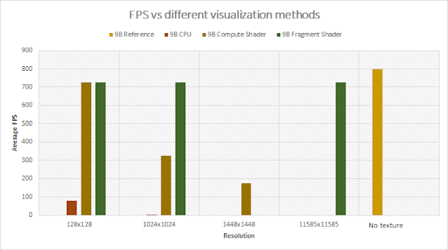 |
| 9 Bodies. FPS values per texturing mode |

|
| Solar system. Outer worlds visible, inner worlds is the blue blob. Fragment shader 5000x5000 |
Test 3: Chaos (36 Bodies)
Modified Solar system to have a total of 36 bodies. |
| 36 Bodies. FPS values per texturing mode |

|
| Modified Solar system with 36 bodies. Fragment shader 3000x3000 |
The data shows that CPU is clearly a bottle neck. Among other methods Fragment is recommended, specially when it concerns increasing the resolution. It has great performance that barely decays with the resolution.
It is worth mentioning that there are factors that can affect the results:
- To improve performance, we could add SystemDiagnostics and calculate the FPS in a stand-alone deployment. The unity editor generates some overhead.
- Create a multi-threading implementation for the CPU approach.
Here I want to visually show the difference between each approach (CPU,
Compute shader and Fragment shader).
The gravitation system has repetitive calculations in the FixedUpdate per object, which in return affect the general FPS. This is easily seen in the Chaos example.
Note: for the tests I had to disable the trail as it was creating a decent overhead in the results, though the GIFs shown here will display the trail.
The gravitation system has repetitive calculations in the FixedUpdate per object, which in return affect the general FPS. This is easily seen in the Chaos example.
Note: for the tests I had to disable the trail as it was creating a decent overhead in the results, though the GIFs shown here will display the trail.
Conclusion
For any type of heavy math operations independent of each other it is highly recommended to use the GPU. The speed at which it processes the data cannot be compared to anything else. It is true the CPU solution does not use multiple threads (which could improve the results considerably), but I doubt it can reach the Fragment Shader’s FPS.This is just a quick post showing how to implement the math using 3 different approaches, and they could be improved. I am not interested in doing a foolproof analysis here, but an initial estimation.
As with the previous post a sample project can be found on this download link with all the relevant code.
Unity version: 2020.2.7f1
Hopefully this can bring my readers some insights.
References
[1] Unity Documentation Texture2D, Version 2020.3, Accessed 21 June 2021, <https://docs.unity3d.com/ScriptReference/Texture2D.html>[2] Unity Documentation Compute shader, Version 2020.3, Accessed 21 June 2021, <https://docs.unity3d.com/Manual/class-ComputeShader.html>
[3] Ronja’s Tutorials Compute Shader, July 26 2020, Accessed 21 June 2021, <https://www.ronja-tutorials.com/post/050-compute-shader/>
[4] Microsoft Documentation, 2021, Accessed 21 June 2021, <https://docs.microsoft.com/en-us/windows/win32/direct3dhlsl/sm5-attributes-numthreads>
[5] Unity Answers, Difference Between Calling numthreads and Dispatch in a Unity Compute Shader, July 25th 2020, Accessed 21 June 2021, <https://stackoverflow.com/questions/63034523/difference-between-calling-numthreads-and-dispatch-in-a-unity-compute-shader>
[6] Nvidia Developer Zone, Cg 3.1 Toolkit Documentation, Accessed 24 June 2021, <https://developer.download.nvidia.com/cg/index_stdlib.html>


